Technical information: Bushing
According to DIN ISO 4379 cylindrical sliding bushings are standardized, ready-to-fit machine parts.
They consist of a backing with cylindrical outer and inner surface to support the sliding layer.
They can absorb higher forces than conventional steel, bronze, or plastic slide bearings and are ideal for pivoting movements and high, unidirectional and variable loads. Used as axial guide bearings, they are also superior to the already mentioned slide bearings.
Please note:
The linear stroke of the shaft in the sliding bushing may not exceed 2.5 x dimensions B or the service life will be significantly reduced.

³ Applies to dimensions d, D and B
Series
Sliding bushings are manufactured as GB...X...X...ZW in the range d = 30-200. The unhardened steel backing/outer ring is mechanically machined accordingly and the sliding layer is applied to the bore. The counter mate (shaft/bolt) is missing and is usually provided by the customer.
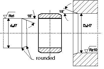
The counter mate should have a surface hardness of HRc ≥ 55 and a roughness of Rz ≤ 1.
Precision
The main dimensions according to DIN ISO 286-2 are toleranced as follows:
Bore diameter d = H8,
Outside diameter D = p7,
Width W = h12.
The shape and position tolerances are within the specifications listed above.
If the sliding bushings GB...x...x...ZW are installed in a housing bore H7 and the shaft/the bolt is manufactured in f7, the resulting operating clearance is in the following ranges (see Table 4:)
| d > 30 - 80 |
d > 80 - 120 |
d > 120 - 200 |
|
| Operating clearance = |
0,030 - 0,080 |
0,060 - 0,090 |
0,060 - 0,100 |
Table 4: Sliding bushing operating clearance
